Depth Buffer
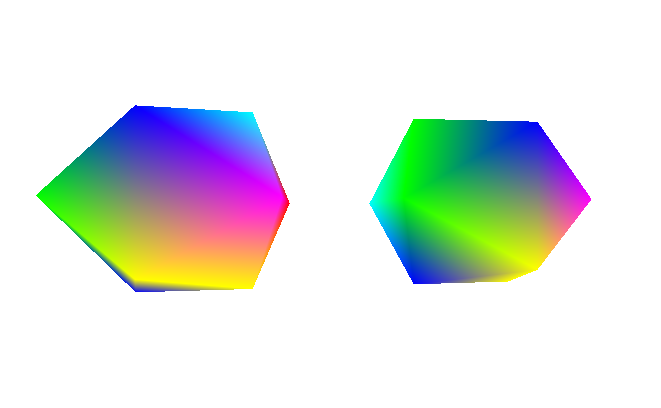
So there’s this issue with the renderer where it can’t really handle multiple objects and non-convex shapes. Below you can see two rainbow icosahedrons to the left along with a diagram representing an overhead view of where the camera is relative to them to the right.
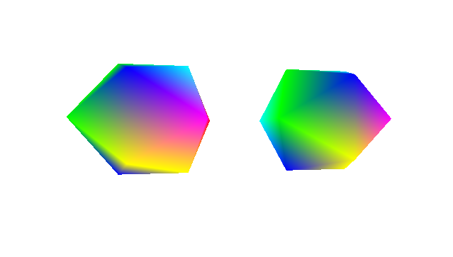
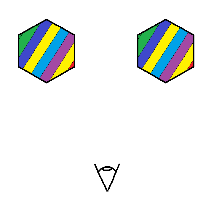
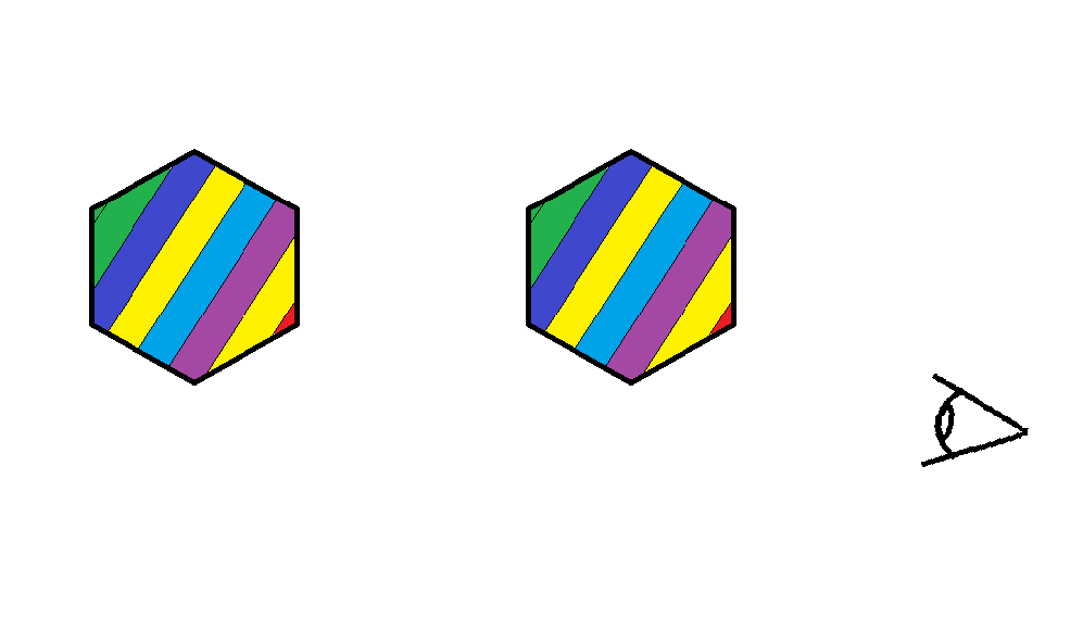
We can see that the left icosahedron is rendered to be in front of the right, even though the right icosahedron is actually in front of the left one in the scene. You can imagine that this would also happen for non-convex geometry as well. If you can’t imagine that then just lie to yourself that you understand what I’m saying. So why is this happening?
The way this works is you have two meshes that contain a bunch of triangle and vertex information. When you feed this into the rendering pipeline it will just rasterize the triangles in the order that they enter into the render pipeline. So if it enters in first then it get’s rendered last. This is a problem because this isn’t how reality works. To alleviate this we would use something called a depth buffer (or a Z buffer). The following is my understanding of what the depth buffer is.
During the triangle vertex projection we take the 3D vertices and we make them 2D. During this phase we essentially divide the x and y components of the 3D point by its z component to get screen coordinates. Normally z gets discarded at this point, but we want to keep it as a per-vertex attribute and pass it along to the rasterization phase. Note that this is the camera-space z (after the view transform), not model-space or world-space z. Model-space z is meaningless for depth since the model could be oriented anywhere.
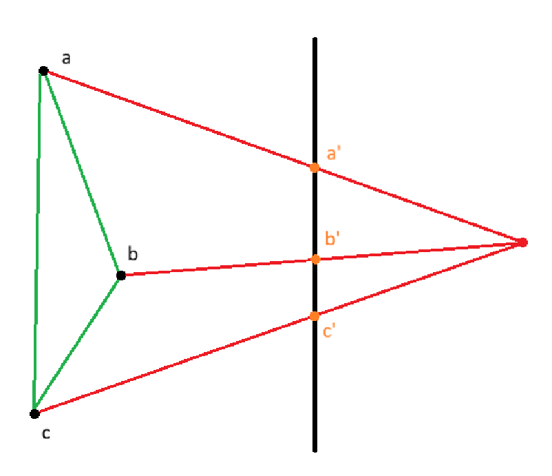
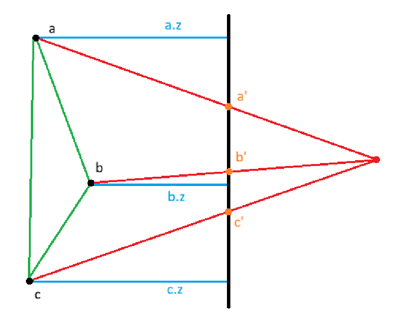
In the image above we can see that the vertices (a, b, c) of the triangle are projected onto the black photo plane. The resultant projected points become (a’, b’, c’). This is how we would normally perform projection, but now we also store the z components of the original vertices (a.z, b.z, c.z).
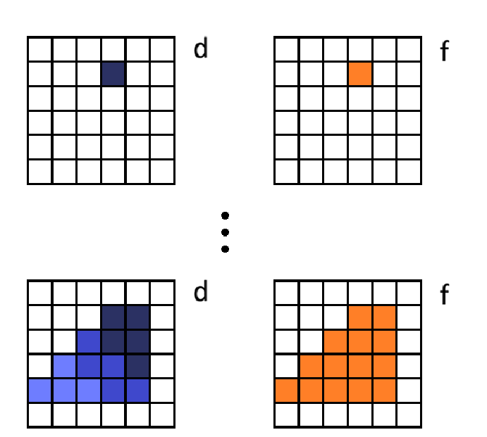
During rasterization we would use these recorded depth values and perform barycentric interpolation to get all the intermediate depth values for the triangle. One problem with this is that linearly interpolating z across screen pixels doesn’t give the correct 3D depth at each pixel. This is because perspective projection compresses 3D space non-uniformly. Equal steps across the screen don’t correspond to equal steps across the 3D triangle.
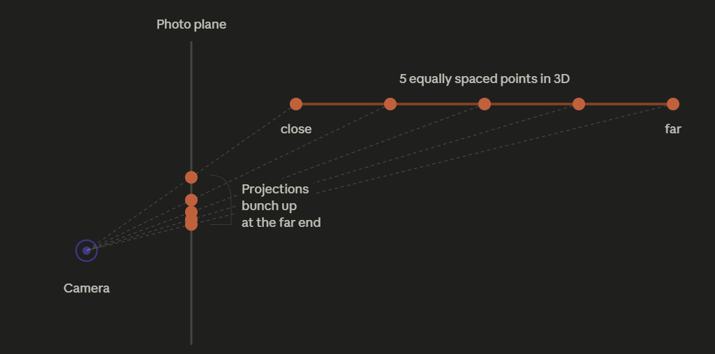
The orange line at the top is a line segment in 3D space, stretching away from the camera (the close end on the left, the far end on the right). I put 5 equally spaced points on it.
Each point projects to the photo plane by drawing a ray from the point back to the camera origin. Where that ray crosses the photo plane is the screen position of that point.
Look at the projections on the photo plane: they are not equally spaced. The first two are far apart. The last three are squished almost on top of each other.
That’s the whole insight. Equal spacing in 3D becomes unequal spacing on the screen. The far end of the line gets compressed into a tiny region of the screen, while the close end spreads out across many pixels.
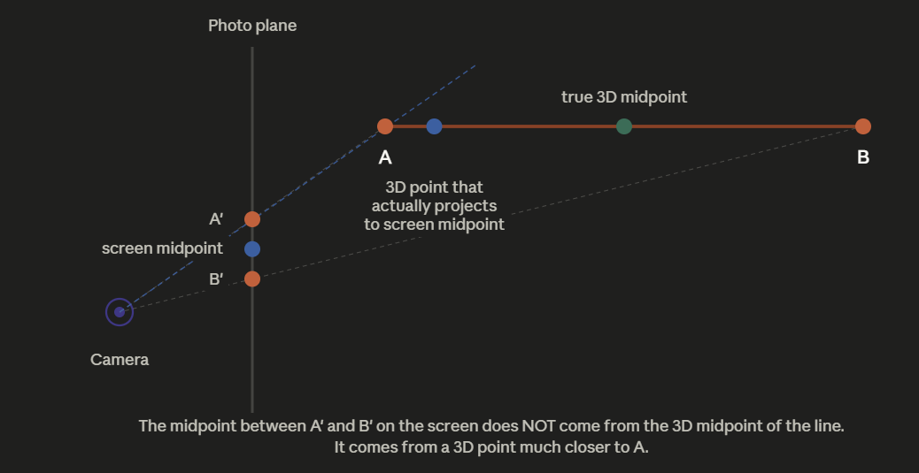
When the rasterizer walks across the projected triangle one pixel at a time, at each pixel it asks “what depth do I assign here?” and answers by linearly interpolating between A’s depth and B’s depth based on how far across the screen it is.
But the diagram just showed that equal screen steps don’t correspond to equal 3D steps. So when the rasterizer is at the screen space midpoint for the geometry it says “we’re halfway across, so depth must be halfway between A and B,” it’s wrong. The screen midpoint actually corresponds to a 3D point much closer to the camera than the 3D midpoint as seen below.
To fix this we would interpolate across screen space using 1/z, instead of z.
Before any rasterization starts, we allocate a depth buffer to have the same dimension as the frame buffer and initialize every element to be zero (representing 1/infinity, since we’ll be storing 1/z values).
When we start to render a triangle we will iterate pixel by pixel within its bounding box.
- Determine if the pixel is in the triangle
- Compute barycentric weights
- Linearly interpolate 1/z at that pixel
- Check if the depth already in that element of the depth buffer is closer to the camera or not. If it is then skip that pixel, otherwise proceed
- Interpolate color
- Write respective values to both buffers
- Repeat for each pixel
Results
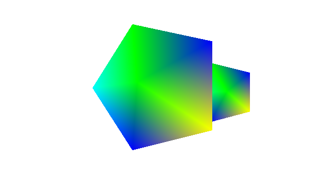
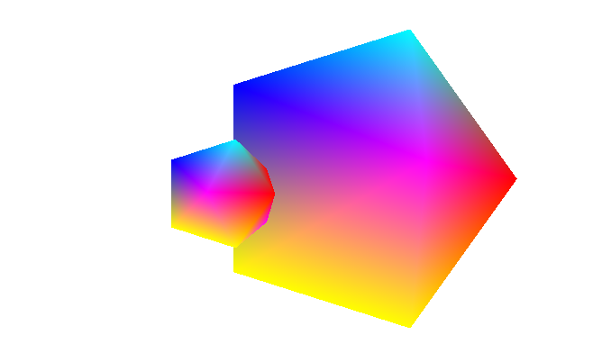
So I’ve just implemented this and this is the result…
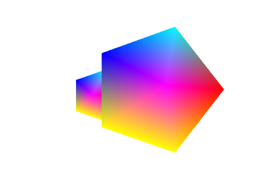
IT WORKS LOOK AT HOW BEAUTIFUL IT IS!!!
Ok now I want to go build a non-convex shape and put that into the renderer.
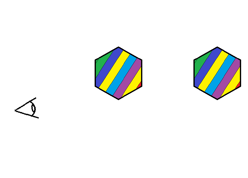
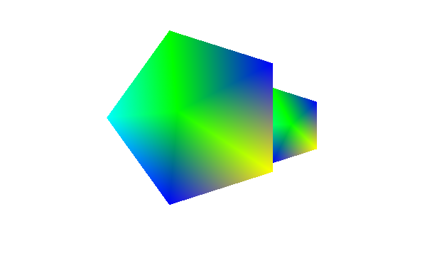
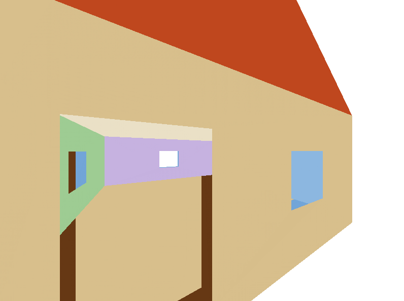
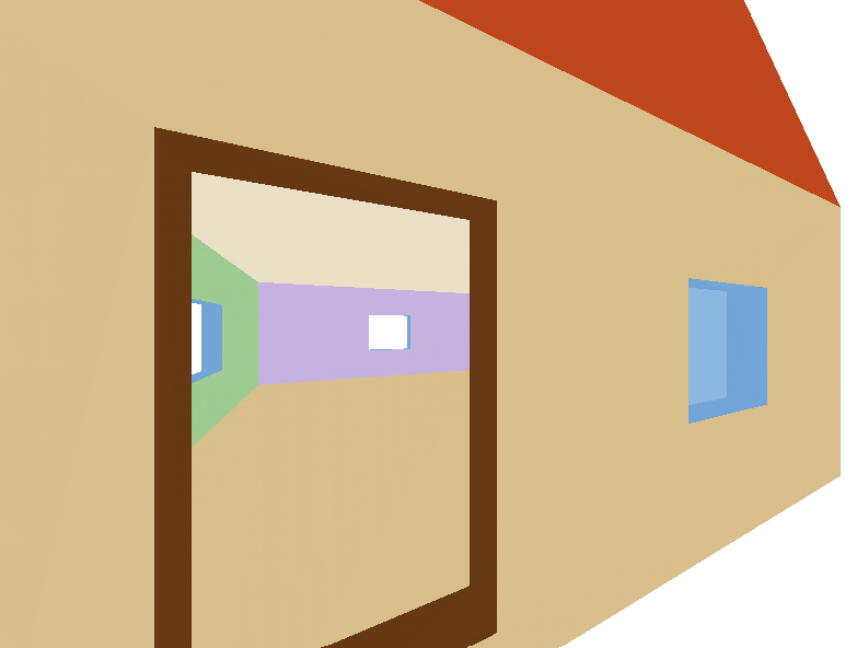
Before Depth Buffer
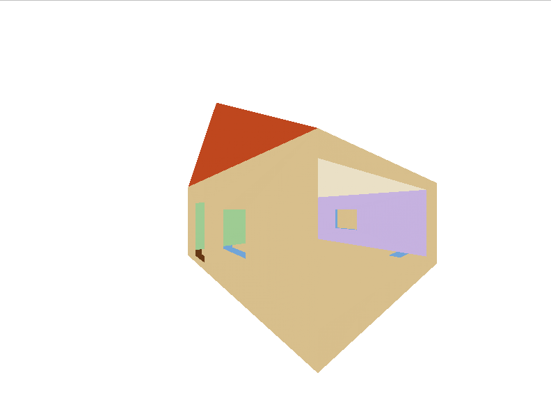
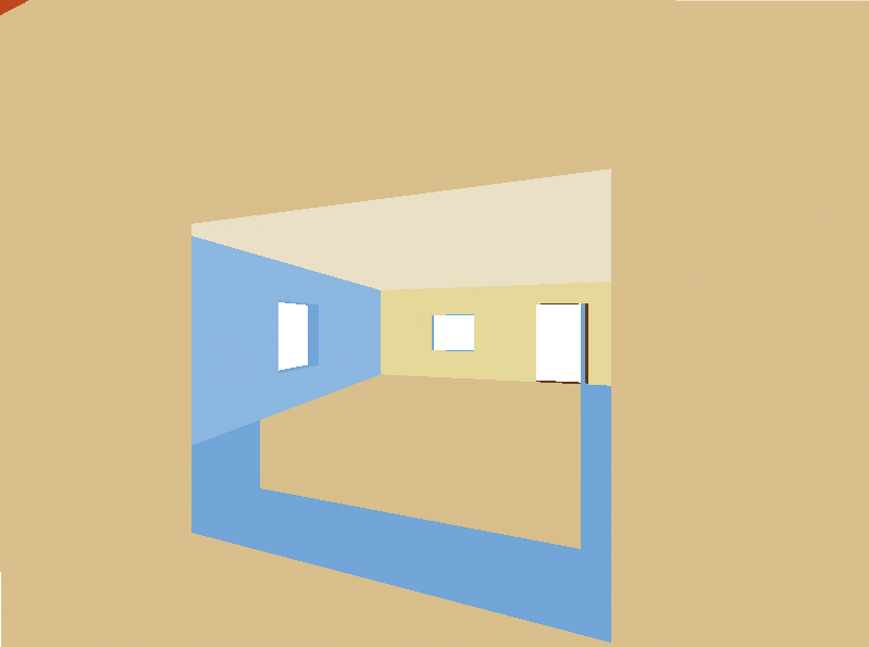
After Depth Buffer

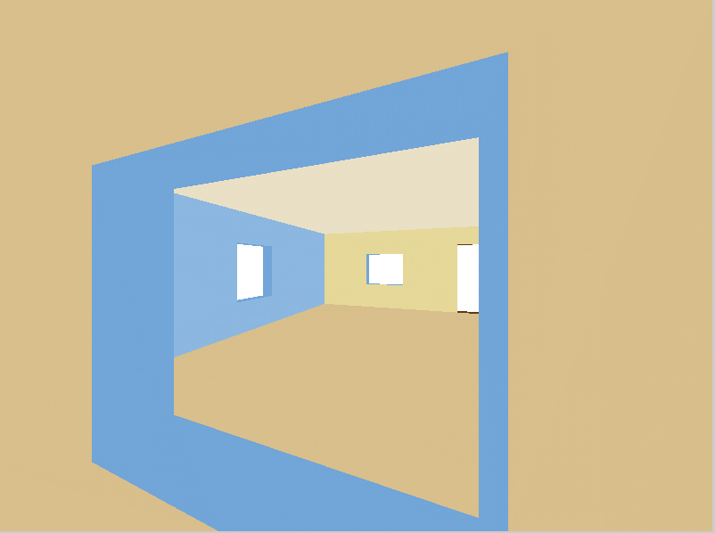
Now my house is beautiful and not glitching out.
Next Steps
One thing is that right now the depth buffer and the frame buffer are two separate unrelated objects. The consequence of this is that I actually can’t render the depth buffer to the viewport because it’s not compatible. Which is a shame because I think it would be cool to see the depth buffer.
- One way to potentially fix this is to refactor the viewport to accept a general visualization buffer, where frame buffer and depth buffer are subclasses.
- Another way would be to have a method in depth buffer that can produce a frame buffer and then pass that to the viewport?
I’m going to have to evaluate which one of these I prefer or think of a third option. Regardless this is a pretty minor thing.
The next BIG feature would be texture. For that I would need to look into UV coordinates and just figure out how to incorporate that into the pipeline.
Another big but boring thing would be cleaning up the repo. There needs to be more README’s, documentation, rectify some questionable design decisions, add Doxygen compilation, get a linter and formatter (surprised I didn’t already have one), etc.